Islanding Phenomenon Detection System

Islanding phenomenon detection systems protect grid connection when connecting dispersed energy resources from new sources of energy (wind power generation and hydraulic power generation), etc. to the power grid with a reverse power flow. These systems incorporate all the protection elements required for grid interconnection with a reverse power flow. Our proprietary interharmonics current injection method is used for active elements to properly detect the islanding phenomenon.

Features

  • Islanding phenomenon is detected quickly and accurately based on the interharmonics current injection method indicated in the Grid-interconnection Code (JEAC 9701-2016).
  • The system can be used for any type and number of pieces of power generation equipment.
  • Mutual intervention is avoided by selecting different injected interharmonic orders even if multiple dispersed energy resources are installed in the same bank.
  • The system incorporates OVs, UVs, DSs, OVGs, OFs, UFs, and all the passive and active elements that are required to protect grid interconnection with a reverse power flow. The applicability must be checked before installation. The applicability, recommended settings, and number of pieces of equipment can be determined based on the results.

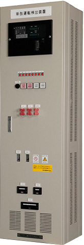
Rating

Operating Temperature Range 0~40℃
Installation Location Indoor
Size (W×D×H) 500×400×1,700mm
Weight 210kg

Q&A

A

The system monitors the impedance (susceptance) on the grid side. Thus, the system can be applied to any power generators (an AC generator [synchronous or induction], a DC generator + an inverter). It can be used for any distributed energy resource such as wind power generation, cogeneration, small low head hydro power, fuel cell, biomass power generation equipment, etc.

A

The system is completely independent from power generators. A single system is required per interconnection point regardless of the number of power generators.

A

The power consumption of the equipment control power source (110 VDC) is 200 W or less. The power consumption of injection power source (single phase 210 V) is 600 W or less

A

The fluctuation range is within −20% to +30% of 110 VDC (88 V to 143 V). The ripple rate should be 5% or less.

A

The expected design service life is 15 years.

A

Electrolytic power capacitors are used in injection circuits. Customers are requested to replace the power capacitors every six years and are recommended to conduct a periodic inspection every year (at least every three years). Interharmonics current injection method for active elements requires special testers. For details, please contact us.

A

As of March 2024, we have delivered over 500 units.

Contact
Contact Us